
After the Great Stink that came from pouring untreated sewage from individual houses into the Thames, London’s Metropolitan Board of Works created marvels of Victorian engineering to prevent that terrible event from recurring by creating technological means of processing sewage and returning clean water to the Thames. The following article from the Illustrated London News goes into great detail in describing the mighty pumps and the steam engines that drove them but doesn’t emphasize in any way the amazing about of energy devoted to beautifying both the exterior and interior of the pumping station. Clearly, the Victorian designers of this most practical of edifices lavished the kind of attention identical to that found on major churches! Ruskin, who in “Traffic” told his audience that their railway embankments and similar major construction projects were the modern equivalents of medieval cathedrals, could have added the Abbey Mills pumping station to these modern equivalents of those cathedrals to which medieval towns and cities devoted their wealth. Of course, Ruskin might also have been very disturbed by the fact that this technological marvel used precisely the kind of Gothic details he had urged his readers to use — but they took form in iron, not stone. — George P. Landow .
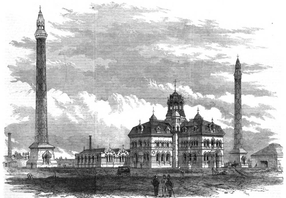
General view of the Abbey Mills Pumping Station. Click on image to enlarge it.

he Abbey Mills pumping-station at West Ham, near Stratford-at-the-Bow, was opened by the chairman of the Metropolitan Board of Works, Sir John Thwaites, with a party of members of the Board and visitors, on the day when they opened the Thames North Embankment to foot-passengers between Westminster Bridge and Essex-street, Strand. The pumping-station at Abbey Mills is a most important portion of the scheme for the main drainage of London. It will be remembered that one prominent feature of the design is the attempt which has been made, as far as possible, to remove the sewage by gravitation, and thus to reduce the pumping to a minimum. It is, however, impossible for sewage to fall by gravitation for a distance of ten or twelve miles from districts which are lower than or near the level of the river, and yet at their outfall to be delivered at the level of high water without the aid of pumping. Thus it happens that all the sewage on the south side of the Thames, and the sewage of a portion of the north side, has to be lifted, and for this purpose there are four pumping-stations, two on each side of the river. Of those on the south side, one is situate at Deptford-creek, of 500 nominal horse-power, and the other at the Crossness outfall, which was opened by the Prince of Wales in April, 1865, and which is also of 600 nominal horsepower. Of the two on the north side, the largest and most important is that of the Abbey Mills, which is 1140 nominal horsepower. The fourth will be the smallest station, being of 240 nominal horse-power only, and situated at Pimlico. Its work is at present performed by a temporary engine. The permanent station awaits the formation of that part of the low-level sewer which is to be constructed under the Chelsea Thames Embankment, the Act for which has just received the Royal assent. The Abbey Mills pumps will lift the sewage of Acton, Hammersmith, Fulham, bhepherd’s Bush, Kensington, Bmtupton, Pimlico, Westminster, the City, Whitechapel, Stepney, Mile-end, Wapping, Limehouse, Bow, and Poplar, representing an area of twenty-five square miles, and a height of 36 ft. from the low-level to the high-level sewers.

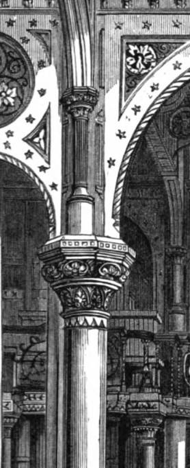
Examples of the ornate decoration on this most practical
The whole of the very extensive works contained in the Abbey Mills pumping station have been constructed after the designs of Mr. J. W. Bazalgette, C.E., engineer-in-chicf to the Metropolitan Board of Works, and under the personal superintendence of Mr. Edmund Cooper, the resident engineer. The buildings have been erected by Mr. W. Webster, contractor, of London. The engines, boilers, and pumping machinery have been made and erected by Messrs. Kothwell and Co., of the Union Foundry, Bolton, Lancashire, one of the oldest engineering establishments in the country.
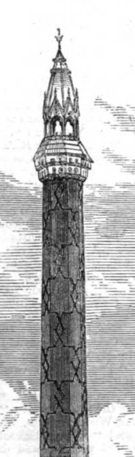
The station covers an area of seven acres, divided into two portions by the northern outfall sewer, which passes diagonally across it on an embankment raised about 17 ft. above the surface. On the south-west side of the embankment stands the engine and boiler houses and chimney-shafts, together with the coal-stores and wharf for landing cools and other materials from Abbey Creek. On the north-east side of the embankment are the cottages for the workmen employed on the works, and a reservoir for storage of water to supply the boilers and condensiug water for the engines. The engine and boiler houses form one building, the engine-house Ixing arranged on a plan in the sliape of a cross, and the boiler houses forming two wings extending north-west and southeast of the north-eastern ann of the cross. The extreme dimensions of the building, taken across two of the arms, is 142 ft. 6 in.; the width of each arm being 47 ft. 6 in. Each of the two boiler-houses measures 100 ft. in length by 62 ft. in width; and there is a workshop situated between the two, measuring 49 ft. 6 in. by 33 ft. The engine-house consists of four stories in height, two of which ore below and two above the surface of the ground, the height of the two lower stories being 38 ft., and that of the two above ground, measured from the engine-room floor to the apex of the roof, being 62 ft. At the intersection of the four arms of the cross the building is covered by a cupola of an ornamental character, rising to a height of 110 ft. from the engine-room floor, and at each of the internal angles of the cross rises a turret in which is formed a circular staircase giving access to the several floors of the building. The boiler-houses are of one story above the finished ground level, the boilers and stoking floor being below that level. The total height from stokehole floor to apex of roof is 33 ft. The style of building adopted is mixed, and the decoration consists of coloured bricks, encaustic tiles, and stone dressings, carved work being introduced at the caps of piers and columns. The chimney-shafts, of which there are two, one on each side of the engine-house, are 209 ft. in height from the finished surface and 8 ft. internal diameter throughout. They are externally octagonal in plan, rising from a square battered base. They correspond in style with the main building, and are similarly enriched with coloured bricks and stone dressings, and are capped at the top by an ornamental cast-iron roof, pierced with openings for the egress of the smoke. The foundations of brickwork and concrete extend to a depth of 36 ft. below the finished surface.

Interior of the Abbey Mills Pumping Station.
The engines, which are aoout 1200-horse power, are eignt in number, of the class known as single-cylinder condensing beam-engines, each having a cylinder 64 in. in diameter, with a stroke of 9 ft., working two double-acting pumps, 4 ft. diameter, with a stroke of 4 ½ ft. direct from a strong cast-iron beam 40 ft. long by 6 ft. deep in the middle, placed overhead upon very richly ornamented cast-iron entablatures and columns. To ease the working of the pumps, there is placed in the centre of the engine-house, below the floor, a large cast-iron air-vessel, 13 ft. diameter and about 20 ft. high, through which the sewage is pumped into a cast-iron tube or culvert, 10½ ft. diameter. There is also a fly-wheel, 28 ft. diameter, weighing about 40 tons, attached to each engine; and to supply them with steam there are sixteen boilers, 30 ft. long by 8 ft. diameter. Any one of the engines, w’hen in working order, is capable of pumping 1,000,000 gallons of sewage per hour.
The sewage is brought into the pump-well, which forms the lowest story of the building, from the low-level sewer, but, before admission, is strained of any extraneous matters which may be brought down with it, and which would either not pass or be detrimental to the pump-valves, by means of cages of wrought-iron bars, which are placed in chambers in front of the engine-house, and which are capable of being lifted and emptied when full. The building containing the machinery and appliances for this purpose stands in front of the centre of the engine-house, and from the chambers beneath it are three sewers conveying the sewage, after being strained, to the pump-wells in three of the arms of the engine-house. From the sewage-well the water is lifted through rectangular cast-iron pipes, situate at the sides of the building, into the sewage-pumps, and it is from them forced through cast-iron cylinders 6 ft. in diameter, running along the centres of three of the arms of the building, and below the engine-room floor into the large cast-iron air-vessel in the centre of the building. From this vessel the sewage is lifted by the power of six engines, and forced, through the huge iron culvert above mentioned, into the outfall sewer, arrangements being made at its junction therewith for regulating the discharge. Provision is made for disconnecting any of the pumps from the discharge culverts. The boilers, of which there are sixteen, are arranged side by side in the length of the building, eight in each house, the stokehole extending from end to end at the rear of the building. The boilers are Cornish cylindrical, 8 ft. in diameter, 30 ft. long, with two tubes, each 3 ft. 3 in. diameter, discharging into the main flue running at the back of the boilers, and extending on each side to the chimney shafts. The coals are brought to the stokeholes by trams from the coal-vaults, which extend the full length of the stokeholes, and on the same level, being below the general surface of the ground, and covered by brick arches supported on brick piers and cast-iron girders. Trams are laid over the coal-vaults communicating with the wharf at Abbey Creek, so that coals can be unladen and discharged into the vaults with the utmost facility, openings being left at intervals in the covering arches of the vaults to permit of the coals being shot into them from the trucks on the tramway above. The coal-vaults cover an area 240 ft. by 102 ft. The reservoir for the storage and purification of the water for the use of the boilers and for condensing purposes is situate on the opposite side of the embankment of the northern outfall sewer. It is constructed mainly of concrete, is 18J ft. in depth, and covers an area of about one acre, which is divided into three compartments, each compartment being used in turn as a settling pond, and containing about one million gallons ; there are inlet pipes to bring water from the creek, and outlet pipes to conve the water to the supplementary reservoir under the engine-room and above the pump-well, from which it is taken direct to the boilers and to the cold-water cisterns around the condensers. The cottages for the workmen are eight in number, arranged in pairs, each containing five rooms, and are fitted with every reasonable convenience; the house for the superintendent of the works, which is situate on the other side of the outfall sewer, and near the entrance to the works, is more commodious, and fitted up in better style. The cottages are all externally relieved by coloured brick bands aud arches, so as to harmonise in some respect with the larger buildings. [162]
Related Material
- The Victorian Environment (homepage)
- From Inconvenience to Pollution -- Redefining Sewage in The Victorian Age
- The Purification of The Thames (Illustrated London News, 1858)
Bibliography
"Leaves from a Sketchbook: Norwich." Illustrated London News 53 (15 August 1868): 161-63. Hathi Trust online version of a copy in the Princeton University Library. Web. 25 May 2021.
Last modified 28 May 2021